Unity - shader의 원근 투영(Perspective projection) 행렬(UNITY_MATRIX_P)을 수작업으로 구성
지난 글에서 월드 행렬과 카메라 행렬을 수작업으로 구성해 봤으니,
Unity - shader의 World matrix(unity_ObjectToWorld)를 수작업으로 구성
; https://www.sysnet.pe.kr/2/0/11633

Unity - shader의 Camera matrix(UNITY_MATRIX_V)를 수작업으로 구성
; https://www.sysnet.pe.kr/2/0/11692
이제 마지막으로 투영 행렬을 구성해 볼 차례입니다. ^^
투영 행렬을 구성하는 요소는 Unity Inspector 창에 보이는 "Field of View", "Clipping Planes"와 게임 화면이 실행되는 윈도우의 "가로/세로" 비율이 됩니다. C# 스크립트에서 이에 대한 값은 각각 다음과 같이 구할 수 있습니다.
Camera camera = Camera.main;

float aspect = camera.aspect; // 또는 (float)camera.pixelWidth / camera.pixelHeight;

float fov = camera.fieldOfView;
float near = camera.nearClipPlane;
float far = camera.farClipPlane;
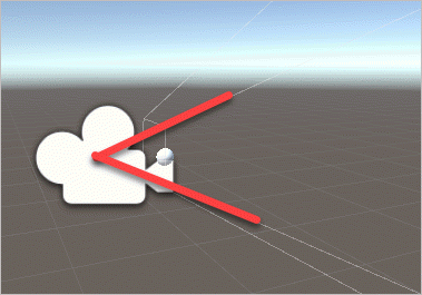
여기서 Field of View는 다음과 같이 Unity에서 카메라로부터 상하로 퍼져 나가는 시야각을 의미하며 화각 또는 FOV라고 줄여서 말하기도 합니다. (Unity 에디터의 기본값은 60도)
near는 기본 값이 0.3인데 월드 좌표계 기준으로 카메라로부터 0.3 만큼 떨어진 "근-평면"의 위치를 의미합니다. Scene을 새로 생성하면 카메라의 기본 위치값이 (0, 1, -10) 좌표이므로 근-평면은 (0, 1, -9.7) 좌표에 위치하게 됩니다.
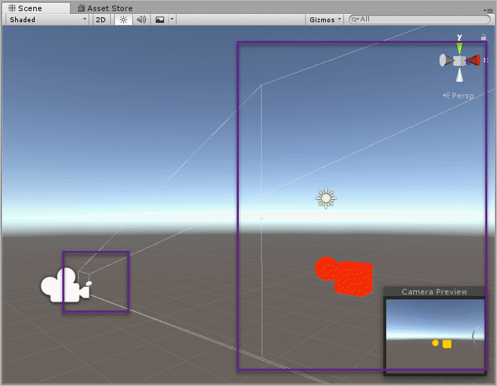
far는 기본 값이 1000이고 월드 좌표계 기준으로 카메라로부터 1000 만큼 떨어진 "원-평면"의 위치를 의미합니다. 마찬가지로 Scene의 기본 값 상태일 때 원-평면은 (0, 1, 990) 좌표에 위치하게 됩니다. 아래는 유니티 편집 화면에서의 근-평면과 원-평면의 모습을 보여줍니다.
FOV와 Near, Far 값은 개발자가 제어할 수 있지만 화면 비율(aspect 값)은 딱히 조정할 수 없습니다. 이건 사용자가 게임을 실행할 때 보통 전체 화면으로 실행하기 때문에 윈도우의 width, height가 고정되거나 "창 모드"로 게임을 실행했을지라도 사용자가 임의로 변경하는 것이기 때문에 개발자 입장에서는 그때마다 aspect 비율을 투영 행렬에 잘 반영하면 됩니다.
이 값들로부터 투영 행렬을 만드는 것은 다음의 책을 보면 잘 나옵니다.
유니티로 배우는 게임 수학  기초 개념부터 모바일까지, 게임 개발에 필요한 수학 원리 설명서
; http://www.yes24.com/24/goods/30119802
자세하게 수학적인 설명과 곁들여 설명하고 있으므로 그 부분에 대해서는 책을 참고하시고, 이 글에서는 해당 투영 행렬을 Unity shader에서 어떻게 구성할 수 있는지에 대한 내용만 알아보겠습니다.
우선, 책에 있는 프로젝션 변환 행렬 P는 다음과 같이 이뤄진다고 소개하고 있습니다.
${
P = \begin{bmatrix} \frac {2n} {r - l} & 0 & \frac {r + l} {r - l} & 0 \\ 0 & \frac {2n} {t - b} & \frac {t + b} {t - b} & 0 \\ 0 & 0 & \frac {-(f + n)} {f - n} & \frac {-2fn} {f - n} \\ 0 & 0 & -1 & 0 \end{bmatrix}
}$
하지만, 저 투영 행렬은 OpenGL의 관례를 따라 나타낸 것이고 각각의 플랫폼에 따른 shader 상의 투영 행렬은 다르다고 합니다. 일례로 (DirectX를 사용하는) 윈도우 데스크톱 환경의 경우에는 다음과 같은 투영 행렬이 사용된다고 설명합니다.
${
P = \begin{bmatrix} \frac {2n} {r - l} & 0 & \frac {r + l} {r - l} & 0 \\ 0 & \frac {-2n} {t - b} & -\frac {t + b} {t - b} & 0 \\ 0 & 0 & \frac {-f} {f - n} & \frac {-fn} {f - n} \\ 0 & 0 & -1 & 0 \end{bmatrix}
}$
수식에 사용된 변수의 의미는 다음과 같습니다.
l == 근-평면의 좌측 끝의 x 좌표
r == 근-평면의 우측 끝의 x 좌표
b == 근-평면의 하단 끝의 y 좌표
t == 근-평면의 상단 끝의 y 좌표
n == 원점으로부터 근-평면까지의 거리
f == 원점으로부터 원-평면까지의 거리
여기서 n과 f는 이미 Unity Inspector 창에서 Camera 객체의 값으로부터 설정된 바로 그 값입니다. 그리고 나머지 left, right, top, bottom의 값은 FOV에 지정된 각을 이용해 탄젠트 삼각함수로 구할 수 있습니다. 가령 top 값은 근-평면 하단 끝의 y 좌표이므로 x축 기준으로 y-z 평면으로 봤을 때,
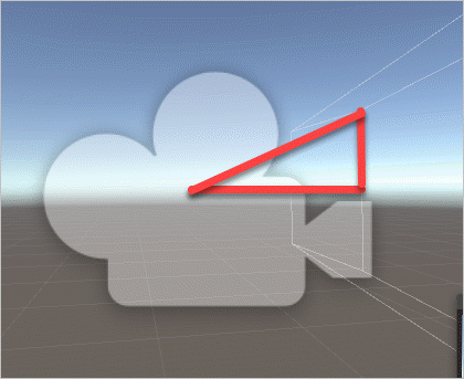
직각 삼각형의 빗변과 밑변의 각도는 Field of View 60도에서 절반인 30도이고 밑변의 길이가 0.3임을 알고 있으므로 top과 bottom은 다음의 공식으로 알아낼 수 있습니다.
top = tan(30°) * near
    = tan(DegreeToRadian(30°)) * near
bottom = -top;
top과 bottom은 쌍을 이루니 당연히 bottom은 -top이 됩니다. 반면 left와 right의 경우에는 FOV를 이용할 수 없습니다. FOV는 시야의 상하각이기 때문인데, 대신 aspect 값이 있으므로 이를 이용해 top을 aspect와 곱해 구할 수 있습니다.
float right = (top * aspect);
float left = -right;
실제로 Unity C# 스크립트로부터 camera.projectionMatrix와 GL.GetGPUProjectionMatrix(camera.projectionMatrix, true)로 구한 행렬의 값은 다음과 같은 식으로 나옵니다. (Unity 기본 Scene 상태를 가정합니다.)
aspect  1.323475        // 사용자의 환경에 따라 변경
tangentFov 0.5773503    // 기본 Scene 상태인 경우
near 0.3                // 기본 Scene 상태인 경우
far 1000                // 기본 Scene 상태인 경우

top 0.1732051
bottom -0.1732051
right   0.2292326
left    -0.2292326
이렇게 해서 소스가 준비되었군요. ^^
이제 Unity C# 스크립트에서 실제 사용하고 있는 행렬을 보겠습니다.
camera.projectionMatrix
1.30871 0.00000  0.00000  0.00000
0.00000 1.73205  0.00000  0.00000
0.00000 0.00000 -1.00060 -0.60018
0.00000 0.00000 -1.00000  0.00000

GL.GetGPUProjectionMatrix(camera.projectionMatrix, true)
1.30871 0.00000 0.00000 0.00000
0.00000 -1.73205 0.00000 0.00000
0.00000 0.00000 0.00030 0.30009
0.00000 0.00000 -1.00000 0.00000
그런데 대충 봐도, (r+l) / (r-l)을 나타내는 projectionMatrix[0,2]의 값이 0인 것을 보면 완전히 똑같은 것은 아닌 것 같습니다. shader에서도 이렇게 쓰고 있는지 다음과 같은 코드로 테스트할 수 있습니다.
v2f vert(appdata v)
{
    float4 pos;

    v2f o;

    float4x4 m = UNITY_MATRIX_P;
    float4x4 projectionMatrix;

    projectionMatrix[0] = float4(m[0].x, 0,      0,      0);
    projectionMatrix[1] = float4(0,      m[1].y, 0,      0);
    projectionMatrix[2] = float4(0,      0,      m[2].z, m[2].w);
    projectionMatrix[3] = float4(0,      0,      -1,     0);

    pos = mul(unity_ObjectToWorld, v.vertex);
    pos = mul(UNITY_MATRIX_V, pos);
    pos = mul(projectionMatrix, pos);

    o.vertex = pos;

    return o;
}
camera.projectionMatrix 및 GL.GetGPUProjectionMatrix의 구조와 동일한 위치의 값만 설정했는데 정상적으로 투영 행렬로 동작하는 것을 확인할 수 있으며 즉, Unity shader에서 사용하는 투영 행렬은 다음의 2개로 정해집니다.
[OpenGL을 따르는 투영 행렬]
${
P = \begin{bmatrix} \frac {2n} {r - l} & 0 & 0 & 0 \\ 0 & \frac {2n} {t - b} & 0 & 0 \\ 0 & 0 & \frac {-(f + n)} {f - n} & \frac {-2fn} {f - n} \\ 0 & 0 & -1 & 0 \end{bmatrix}
}$
[실행 환경에 맞는 투영 행렬 - 아래는 DirectX를 사용하는 윈도우 환경에서의 투영 행렬]
${
P = \begin{bmatrix} \frac {2n} {r - l} & 0 & 0 & 0 \\ 0 & \frac {-2n} {t - b} & 0 & 0 \\ 0 & 0 & \frac {-f} {f - n} & \frac {-fn} {f - n} \\ 0 & 0 & -1 & 0 \end{bmatrix}
}$
그럼 끝났군요. ^^ 재료를 이용해 다음과 같이 투영 행렬을 구할 수 있습니다.
Matrix4x4 myProjection1 = new Matrix4x4();
myProjection1[0, 0] = (2 * near) / (right - left);
myProjection1[1, 1] = (2 * near) / (top - bottom);
myProjection1[2, 2] = -(far + near) / (far - near);
myProjection1[2, 3] = -(2 * far * near) / (far - near);
myProjection1[3, 2] = -1;

Matrix4x4 myProjection2 = new Matrix4x4();
myProjection2[0, 0] = (2 * near) / (right - left);
myProjection2[1, 1] = -(2 * near) / (top - bottom);
myProjection2[2, 2] = -far / (far - near);
myProjection2[2, 3] = -(far * near) / (far - near);
myProjection2[3, 2] = -1;
바로 저 2개의 행렬들은 Unity C# 스크립트에서 다음의 코드로 대응합니다.
myProjection1 == camera.worldToCameraMatrix
myProjection2 == GL.GetGPUProjectionMatrix(camera.projectionMatrix, true);
또한 우리가 구한 l, r, b, t, n, f의 값들이 실제로 camera.worldToCameraMatrix.decomposeProjection 값들과 동일합니다.
camera.projectionMatrix.decomposeProjection
		left	-0.2292326
		right	0.2292326
		bottom	-0.1732051
		top	    0.1732051
		zNear	0.3
		zFar	1000.134

GL.GetGPUProjectionMatrix(camera.projectionMatrix, true).decomposeProjection
		left	0.2293702
		right	-0.2293702
		bottom	-0.1733091
		top	    0.1733091
		zNear	-0.3001801
		zFar	0.3
다음 단계로 Unity shader에서 사용하는 투영 행렬이 camera.projectionMatrix 인지, GL.GetGPUProjectionMatrix 반환 값인지는 다음과 같은 코드로 쉽게 확인할 수 있습니다.
using UnityEngine;

[ExecuteInEditMode]
public class SetMatrix : MonoBehaviour {

    void Start () {
    }

    void Update () {
        Camera camera = Camera.main;

        Matrix4x4 projectionMatrix = GL.GetGPUProjectionMatrix(camera.projectionMatrix, true);
        Shader.SetGlobalMatrix("_projectionMatrix1", projectionMatrix);

        Shader.SetGlobalMatrix("_projectionMatrix2", camera.projectionMatrix);
    }
}
float4x4 _projectionMatrix;
float4x4 _projectionMatrix2;

v2f vert(appdata v)
{
    float4 pos;

    v2f o;

    pos = mul(unity_ObjectToWorld, v.vertex);
    pos = mul(UNITY_MATRIX_V, pos);

    pos = mul(_projectionMatrix1, pos);
    // pos = mul(_projectionMatrix2, pos);

    o.vertex = pos;

    return o;
}
실제로 실행해 보면 GL.GetGPUProjectionMatrix가 반환한 투영 행렬이 정상적으로 동작하는 것을 볼 수 있습니다. 약간 혼란스러운 점이 있다면, C# 스크립트에서 넘겨줄 때의 행렬 값이 다음과 같은 반면,
GL.GetGPUProjectionMatrix

0.97183  0.00000  0.00000 0.00000
0.00000 -1.73205  0.00000 0.00000
0.00000  0.00000  0.00030 0.30009
0.00000  0.00000 -1.00000 0.00000
"Visual Studio Graphics Analyzer"로 디버깅 환경의 Watch 창에서 GL.GetGPUProjectionMatrix의 값을 보면 다음과 같다는 것입니다.
_projectionMatrix1      float4x4
    _projectionMatrix1[0]   x = 0.971829400, y = 0.000000000, z = 0.000000000, w = 0.000000000
    _projectionMatrix1[1]   x = 0.000000000, y = -1.732051000, z = 0.000000000, w = 0.000000000
    _projectionMatrix1[2]   x = 0.000000000, y = 0.000000000, z = 0.000300050, w = -1.000000000
    _projectionMatrix1[3]   x = 0.000000000, y = 0.000000000, z = 0.300090000, w = 0.000000000
즉, 전치가 되어 있는데 이것은 아마도 Visual Studio의 디버거 창이 자동으로 전치를 해주는 것인지? 아니면 메모리 상의 값을 읽을 때 열/행우선을 잘못 판단한 것인지는 알 수 없으나 C# 스크립트 상에서의 디버거 값이 올바른 형식입니다.
정리해 보면, Unity에서 제공하는 투영 행렬은 2가지가 있습니다.
- camera.projectionMatrix == OpenGL을 따르는 형식
- GL.GetGPUProjectionMatrix == Unity 프로그램이 실행되는 환경에 부합하는 투영 행렬(일례로 위에서의 _projectionMatrix1 값은 DirectX 11을 사용하는 윈도우 환경에서 유효한 투영 행렬)
휴~~~ 이것으로 대충 정리가 되었군요. ^^ 행렬의 생성 규칙과 그 값의 decomposeProjection을 알게 되었으니 이제 나머지 단계는 unity shader에서 decomposeProjection에 해당하는 값을 어떻게 구하느냐에 달려 있습니다.
unity shader에서 근-평면/원-평면은 내장 변수를 통해 값을 구할 수 있습니다.
_ProjectionParams float4

x is 1.0 (or ?1.0 if currently rendering with a flipped projection matrix)
y is the camera’s near plane
z is the camera’s far plane
w is 1/FarPlane
float nearPlane = _ProjectionParams.y;
float farPlane = _ProjectionParams.z;

// 기본값인 경우 nearPlane == 0.3, farPlane == 1000
또한 aspect 비율도 _ScreenParams 내장 변수를 통해 구할 수 있습니다.
float width = _ScreenParams.x;
float height = _ScreenParams.y;

float aspect = width / height;
문제는, FOV 값인데 이것은 unity가 내장 변수로 제공하지 않습니다. 대신 기존 UNITY_MATRIX_P로부터 구해올 수는 있습니다. 이에 대한 계산이 재미있는데요. ^^ 이전에 행렬을 구하는 것에서 (0,0)의 값은 다음과 같이 이뤄집니다.
[0, 0] = (2 * near) / (right - left);
그런데 검색해 보면 다음의 소스 코드를 통해,
https://github.com/g-truc/glm/blob/master/glm/ext/matrix_clip_space.inl

template<typename T>
GLM_FUNC_QUALIFIER mat<4, 4, T, defaultp> perspectiveLH_NO(T fovy, T aspect, T zNear, T zFar)
{
    assert(abs(aspect - std::numeric_limits<T>::epsilon()) > static_cast<T>(0));

    T const tanHalfFovy = tan(fovy / static_cast<T>(2));

    mat<4, 4, T, defaultp> Result(static_cast<T>(0));
    Result[0][0] = static_cast<T>(1) / (aspect * tanHalfFovy);
    Result[1][1] = static_cast<T>(1) / (tanHalfFovy);
    Result[2][2] = (zFar + zNear) / (zFar - zNear);
    Result[2][3] = static_cast<T>(1);
    Result[3][2] = - (static_cast<T>(2) * zFar * zNear) / (zFar - zNear);
    return Result;
}
"1 / (aspect * tanHalfFovy) = UNITY_MATRIX_P[0].x"와 같다는 것을 알 수 있습니다. 따라서 각도는 다음과 같이 구할 수 있습니다.
aspect * tanHalfFovy * UNITY_MATRIX_P[0].x = 1
tanHalfFovy = 1 / (aspect * UNITY_MATRIX_P[0].x)

radian_FOV = arctan(1 / (aspect * UNITY_MATRIX_P[0].x))
자, 그럼 다 끝났군요. ^^ 이제 다음과 같이 UNITY_MATRIX_P를 재조립해 적용할 수 있습니다.
Shader "Unlit/NewUnlitShader"
{
    Properties
    {
    }
    SubShader
    {
        Tags{ "LightMode" = "ForwardBase" }

        Pass
        {
            CGPROGRAM
            #pragma vertex vert
            #pragma fragment frag
            #pragma enable_d3d11_debug_symbols

            #include "UnityCG.cginc"

            struct appdata
            {
                float4 vertex : POSITION;
            };

            struct v2f
            {
                float4 vertex : SV_POSITION;
            };

            float4x4 _projectionMatrix;

            v2f vert(appdata v)
            {
                float4 pos;

                v2f o;

                float nearPlane = _ProjectionParams.y;
                float farPlane = _ProjectionParams.z;

                float width = _ScreenParams.x;
                float height = _ScreenParams.y;
                float aspect = width / height;

                float4x4 m = UNITY_MATRIX_P;

                float halfFov = atan2(1, aspect * m[0].x);

                float top = tan(halfFov) * nearPlane;
                float bottom = -top;

                float right = (top * aspect);
                float left = -right;

                // DirectX를 사용하는 윈도우 환경에서의 투영 행렬
                float p00 = (2 * nearPlane) / (right - left);
                float p11 = -(2 * nearPlane) / (top - bottom);
                float p22 = -farPlane / (farPlane - nearPlane);
                float p23 = -(farPlane * nearPlane) / (farPlane - nearPlane);

                float4x4 projectionMatrix;
                projectionMatrix[0] = float4(p00, 0,   0,   0);
                projectionMatrix[1] = float4(0,   p11, 0,   0);
                projectionMatrix[2] = float4(0,   0,   p22, p23);
                projectionMatrix[3] = float4(0,   0,   -1,  0);

                pos = mul(unity_ObjectToWorld, v.vertex);
                pos = mul(UNITY_MATRIX_V, pos);
                pos = mul(projectionMatrix, pos);
                // pos = mul(UNITY_MATRIX_P, pos);

                o.vertex = pos;

                return o;
            }

            fixed4 frag(v2f i) : SV_Target
            {
                return fixed4(1, 0, 0, 0);
            }

            ENDCG
        }
    }
}
참고로
https://github.com/g-truc/glm/blob/master/glm/ext/matrix_clip_space.inl 소스 코드를 보면 알 수 있지만 동일한 값을 다음과 같이 다르게 구하고 있습니다.
projectionMatrix[0, 0] = (2 * near) / (right - left);
                       = 1.0 / (aspect * halfFov)

projectionMatrix[1, 1] = -(2 * near) / (top - bottom);
                       = -1.0 / halfFov;

projectionMatrix[2, 2] = -far / (far - near);
projectionMatrix[2, 3] = -(far * near) / (far - near);
projectionMatrix[3, 2] = -1;
2개의 공식이 왜 같은지는 다음과 같이 풀어 보면 쉽게 이해할 수 있습니다.
(2 * near) / (right - left)
 = (2 * near) / (right * 2) // 어차피 left == -right이므로.
 = near / right             // 공통 인수 2 약분
 = near / (top * aspect)    // right = top * aspect이므로.
 = near / (halfFov * near * aspect) // top = halfFov * near
 = 1 / (halfFov * aspect)   // 공통 인수 near 약분

-(2 * near) / (top - bottom)
 = -(2 * near) / (2 * top)  // 어차피 bottom == -top이므로.
 = -near / top              // 공통 인수 2 약분
 = -near / (halfFov * near) // top = halfFov * near
 = -1 / halfFov             // 공통 인수 near 약분
그러니까 결국, left, right, bottom, top을 구할 필요가 없었던 것입니다. 따라서 shader에서의 소스 코드는 다음과 같이 더 간단해집니다.
v2f vert(appdata v)
{
    float4 pos;

    v2f o;

    float nearPlane = _ProjectionParams.y;
    float farPlane = _ProjectionParams.z;

    float width = _ScreenParams.x;
    float height = _ScreenParams.y;
    float aspect = width / height;

    float4x4 m = UNITY_MATRIX_P;

    float halfFov = atan2(1, aspect * m[0].x);

    // DirectX를 사용하는 윈도우 환경에서의 투영 행렬
    float p00 = 1 / (tan(halfFov) * aspect);
    float p11 = -1 / tan(halfFov);
    float p22 = -farPlane / (farPlane - nearPlane);
    float p23 = -(farPlane * nearPlane) / (farPlane - nearPlane);

    float4x4 projectionMatrix;
    projectionMatrix[0] = float4(p00, 0,   0,   0);
    projectionMatrix[1] = float4(0,   p11, 0,   0);
    projectionMatrix[2] = float4(0,   0,   p22, p23);
    projectionMatrix[3] = float4(0,   0,   -1,  0);

    pos = mul(unity_ObjectToWorld, v.vertex);
    pos = mul(UNITY_MATRIX_V, pos);
    pos = mul(projectionMatrix, pos);
    // pos = mul(UNITY_MATRIX_P, pos);

    o.vertex = pos;

    return o;
}
그 외에 여유가 되시면 Unity가 아닌 실제 카메라 영상을 기준으로 한 다음의 설명도 읽어보시고. ^^
카메라 캘리브레이션 (Camera Calibration)
; http://darkpgmr.tistory.com/32?category=460965
[이 글에 대해서 여러분들과 의견을 공유하고 싶습니다. 틀리거나 미흡한 부분 또는 의문 사항이 있으시면 언제든 댓글 남겨주십시오.]