아두이노에서 적외선 수신기 기본 사용법
우선 이 글에서 사용한 적외선 수신에 대한 부품 먼저 소개합니다.
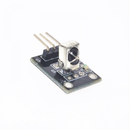
구매 링크는 다음과 같습니다.
아두이노 KY-022 적외선 센서 수신기 모듈(AS0150)
; http://arduinostory.com/goods/goods_view.php?goodsNo=1000000150

제조사: 애니벤더
원산지: 중국
사양:
    전압: 5V
    포트: 디지털 레벨
    전송 거리: 1~8m
    플랫폼: Arduino 마이크로 컨트롤러
    크기: 가로 14mm x 세로 20mm x 높이 10mm
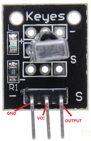
말도 안 된다고 생각하시겠지만 별도의 datasheet는 없었습니다. 그렇다면 도대체 어떤 핀이 어느 용도인지 어떻게 알아낼 수 있을까요? 다행히 검색을 해보면,
KY-022 Infrared IR Sensor Receiver Module For Arduino
; https://forum.banggood.com/forum-topic-28885.html
다음과 같은 그림으로 쉽게 확인할 수 있습니다.
또는 아래의 제품과 아주 동일한 것 같지는 않은데,
KY-022 Infrared Receiver Module
; https://arduinomodules.info/ky-022-infrared-receiver-module/

Operating Voltage 2.7 to 5.5V
Operating Current 0.4 to 1.5mA
Reception Distance 18m
Reception Angle ±45°
Carrier Frequency 38KHz
Low Level Voltage 0.4V
High Level Voltage 4.5V
Ambient Light Filter up to 500LUX
핀에 대한 정보가 다음과 같이 있습니다.
| KY-012 |
Arduino |
| S |
Signal |
| Middle |
+5V |
| - |
GND |
실제로 제가 구매한 IR 수신기 역시 위와 같이 보드에 좌측으로 "-" 표시와 우측으로 "S"가 있었고 테스트 결과 그 핀 배열로 동작했습니다. 일단 이렇게 핀만 확인하면 해당 제품에는 저항이 포함되어 있기 때문에 별도의 부가 저항 없이 곧바로 다음과 같이 간단한 회로 구성으로 사용할 수 있습니다.
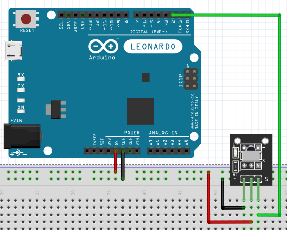
남은 작업은 코딩인데요, Arduino IDE에서 "Sketch" / "Include Library" / "Manager Libraries..."를 이용해 "IRRemote"를 검색하면 "shirriff"라는 사람이 만든 모듈을 구할 수 있습니다. 그것을 추가하고 github에 공개된 원본 소스와 예제 코드에 따라,
z3t0/Arduino-IRremote
; https://github.com/z3t0/Arduino-IRremote
원하는 작업을 추가합니다. 제 경우에 2번 핀에 연결했기 때문에 다음과 같이 초기화하고,
#include <boarddefs.h>
#include <IRremote.h>
#include <IRremoteInt.h>
#include <ir_Lego_PF_BitStreamEncoder.h>

int RECV_PIN = 2;
IRrecv irrecv(RECV_PIN);
decode_results results;

void setup() {
  Serial.begin(9600);
  irrecv.enableIRIn(); // Start the receiver
}
loop에서는
https://github.com/z3t0/Arduino-IRremote 코드에서 구한 dump 함수를 이용해 적외선 신호가 수신될 때마다 그 값을 Serial 출력에 나오도록 만들었습니다.
void dump(decode_results *results) {
  // Dumps out the decode_results structure.
  // Call this after IRrecv::decode()
  int count = results->rawlen;
  if (results->decode_type == UNKNOWN) {
    Serial.print("Unknown encoding: ");
  }
  else if (results->decode_type == NEC) {
    Serial.print("Decoded NEC: ");
  }
  else if (results->decode_type == SONY) {
    Serial.print("Decoded SONY: ");
  }
  else if (results->decode_type == RC5) {
    Serial.print("Decoded RC5: ");
  }
  else if (results->decode_type == RC6) {
    Serial.print("Decoded RC6: ");
  }
  else if (results->decode_type == PANASONIC) {
    Serial.print("Decoded PANASONIC - Address: ");
    Serial.print(results->address, HEX);
    Serial.print(" Value: ");
  }
  else if (results->decode_type == LG) {
    Serial.print("Decoded LG: ");
  }
  else if (results->decode_type == JVC) {
    Serial.print("Decoded JVC: ");
  }
  else if (results->decode_type == AIWA_RC_T501) {
    Serial.print("Decoded AIWA RC T501: ");
  }
  else if (results->decode_type == WHYNTER) {
    Serial.print("Decoded Whynter: ");
  }
  Serial.print(results->value, HEX);
  Serial.print(" (");
  Serial.print(results->bits, DEC);
  Serial.println(" bits)");
  Serial.print("Raw (");
  Serial.print(count, DEC);
  Serial.print("): ");

  for (int i = 1; i < count; i++) {
    if (i & 1) {
      Serial.print(results->rawbuf[i]*USECPERTICK, DEC);
    }
    else {
      Serial.write('-');
      Serial.print((unsigned long) results->rawbuf[i]*USECPERTICK, DEC);
    }
    Serial.print(" ");
  }
  Serial.println();
}

void loop() {
  if (irrecv.decode(&results) == true)
  {
    Serial.println(results.value, HEX);
    dump(&results);
    irrecv.resume();
    return;
  }

  delay(100);
}
테스트를 위해 ^^ 우리 집에 있는 형광등 On/Off 리모컨을 4번 써서 수신하니 각각 다음의 데이터가 들어왔습니다.
33E09F86
Unknown encoding: 33E09F86 (32 bits)
Raw (26): 3550 -1750 600 -400 600 -1800 550 -450 600 -450 600 -1800 550 -450 600 -450 600 -500 600 -450 600 -400 650 -400 550

33E09F86
Unknown encoding: 33E09F86 (32 bits)
Raw (26): 3550 -1750 600 -400 600 -1800 550 -450 600 -450 600 -1800 550 -450 600 -450 600 -450 650 -450 550 -450 600 -450 550

33E09F86
Unknown encoding: 33E09F86 (32 bits)
Raw (26): 3600 -1700 650 -400 600 -1750 600 -400 600 -500 600 -1750 600 -400 650 -400 600 -500 600 -450 600 -450 600 -400 600

33E09F86
Unknown encoding: 33E09F86 (32 bits)
Raw (26): 3600 -1750 600 -400 600 -1750 600 -400 650 -450 600 -1750 600 -400 650 -400 600 -500 600 -450 600 -450 600 -400 600
보는 바와 같이 매번 동일한 데이터가 들어오진 않습니다. 그래도 크게 상관은 없고 저 중에 하나를 뽑아서 IR 송신기로 그대로 보내기만 하면 동작합니다. (
송신에 대해서는 다음 글에서 다룹니다. ^^)
첨부 파일은 이 글의 전체 소스 코드와 회로 그림에 대한 원본 fzz 파일이 들어 있습니다. 또한 아래는 KY-022 Infrared Receiver Module에 대한 Fritzing 부품 파일입니다.
KY-022 Infrared Receiver Module Zip File
; https://arduinomodules.info/download/ky-022-infrared-receiver-module-zip-file/
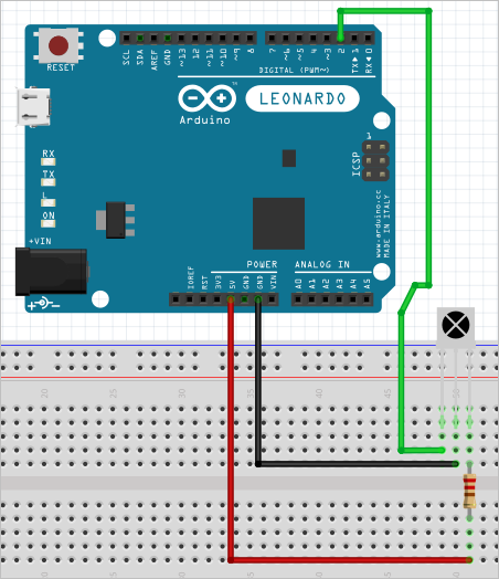
참고로, 제가 가진 IR Receiver 중에는 이 글에서 소개한 보드 일체형 제품이 아닌, 아래와 같이 단지 핀 3개만을 가진 IR Receiver 단품도 있습니다.
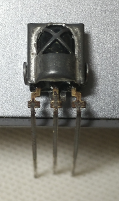
위와 같은 단품을 쓸 때는 이 글에서 설명한 대로 회로를 구성하면 안 됩니다. 왜냐하면 보드의 경우에는 저항을 자체 포함해서 제공했으므로 상관이 없지만 위의 부품만을 연결할 때는 5V 입력 단자에 저항을 하나 연결하는 것이 좋습니다. 게다가 핀에 대한 연결도 바뀌는데요, 왜냐하면 원래 단품 IR Receiver가 위의 그림 기준으로 왼쪽부터 Signal - GND - Vcc이기 때문입니다. (보드 일체형 제품의 경우에는 저 배열을 보드 상에서 바꿔 GND - Vcc - Signal로 제공하는 것입니다.)
그래서 튀어나온 면 기준으로 다음과 같이 회로를 구성해야 합니다.
Fritzing Parts - Homautomation
; http://www.homautomation.org/fritzing-parts/
[이 글에 대해서 여러분들과 의견을 공유하고 싶습니다. 틀리거나 미흡한 부분 또는 의문 사항이 있으시면 언제든 댓글 남겨주십시오.]